The early morning’s and late nights are starting to take their toll now, Wednesday night I loaded the two complete rear batt boxes and wired up the Soliton Jr to the IGN 12V feed and wired the Contactor (big HV relay) with the batteries not connected I turned the Ignition key to hear the gorgeous sound of the HV contactor “click” the HV relay shortly followed by the whir of the Soliton Jr fans.
ITS ALIVE (Well almost)
1st Low voltage live test complete, hurrah!
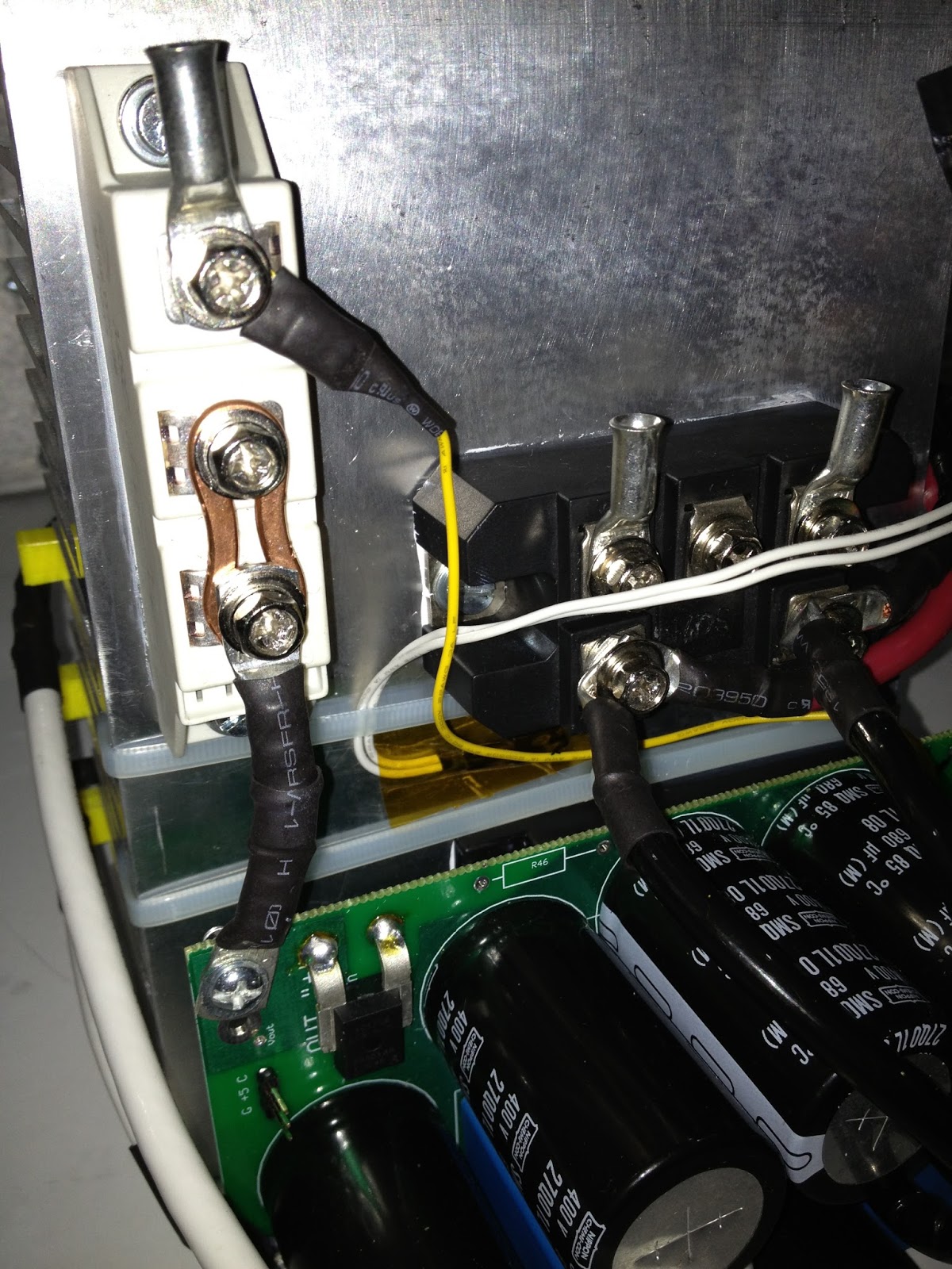
Boyed by that success and due to the failing light now summer is nearing its end I went inside to fire up the charger for it’s 1st Low voltage 12V test and ½ second in LCD came on as expected began boot up “Snap", "Crackle" – I did not wait for the POP!
Fried a 2n2222 transistor, must be a short will investigate tonight ,still looked promising there for a split second.
(Update:- checked this last night and spotted my schoolboy error, I had inadvertently reverse orientated the LM211P IC that feeds the S3 2n2222, DUMMY!)
Ho Hum, I am guessing it has fried the LM211P although it appears that the 2n2222 S3 has taken the brunt of the damage, luckily I have these in stock so I have fired of a post to the diyelectriccar forum’s 10KW charger thread to see if Valery can suggest the symptoms of a fugged LM 211P, this is so that if I replace the definitely fried 2n2222 (S3) and orientate the LM211P correctly I am hoping that I may not have fried the LM211P and it may well be still useable.
If Valery suggests the symptoms of a dead LM211P I should be able to test it and identify if I have killed it or not.
Last night (Thursday 5th) I wired the motor for series field mode clockwise orientation (not sure if it needs clockwise or anticlockwise to give forward motion through the transverse gearbox but I am taking a wild guess at clockwise due to the layout and logical look of how it is laid out. If it is wrong it’s very simple to change.
Also wired in a temporary throttle cable by twisting 2 pairs in an old shielded DIN cable I had laying around (this is definitely not good enough for actual use but I have already ordered an appropriate cable just waiting for it to arrive) basically using 2 cores twisted together to cover the potential 1A current draw (although it will likely be much less as it is only a 5V hall effect sensor probably draws micro/milli amps)
(Update:- The cable I bought turned up and is thinner than I thought So my temporary bodge is probably better than this anyway! Will check with Steve as to what is actually required for Safety’s sake)
Also the new 12V cables arrived 5 meters of each, black and red, silicone insulated, ran these through the car from front to back (in the case of the red +ve) and a short link for the –ve to chassis.
Threaded the red alongside the HV cables, both the HV cables and the 12V +ve are currently just zip fastened to the brake fluid lines in the tunnel that runs under the center down the whole length of the car, this is definitely not safe and once the car is running it will be going back to Brent for him to safely secure all the wiring looms in place properly.
Sunday, 8 September 2013
Tuesday, 3 September 2013
Last week before the Brighton Mini Maker Fair!
Ok, it's the big push.
Met Steve at SMD (the mechanics) on Friday 30th to get a lesson in how to wire a 220V EV battery without killing yourself.
Unfortunately the neoprene tape I had ordered was taking a little longer to arrive than I had expected and was not there on Friday so we used Gaffer tape and some foam tape I had as a temporary replacement and I wired a box (1 of 3) with Steve looking on to make sure I knew what I was doing, Steve suggested a good idea of using elastic bands to separate the banks from each other and the positives in each bank from the negatives in each bank, this way it is much easier to follow what you are doing closely double checking each and every connection you make (one wrong positive from a different bank and BANG say goodbye to a finger potentially, wiring a LIPO battery is not for the faint of heart)
Anyway after a lot of talking with Steve on how to wire the car, towed it home from the mechanics back to mine a 5 min journey, with Steve at the wheel (thanks again Steve) and by Friday at around 4:30PM the car was at my home ready for the final stage wiring!
Saturday 31st Aug
Neoprene arrived this morning so I was able to get straight down to wiring up the batteries proper, I had two wiring layout options I went for the slightly more complicated to wire up method which would give a better end layout of the buss bars in the top of the boxes, following Steve’s advice as how to wire them (slowly checking every connection from each banded bundle wiring only 1 buss bar at a time and then insulating it completely with the wide neoprene self-adhesive tape before moving on to the next one.
Once I had done all the buss bars I moved onto the LVC/HVC cut-off boards Steve had forgotten to bring the HVC/LVC extender boards, so I picked them up on Sunday, Thanks again Steve for being available at weekends.
I also picked up a HV fuse and contactor set from Steve, Forgot to pick up the magnets for the throttle position sensor (TPS) however, my ever loving partner picked these up yesterday (Monday 2nd) as she is as keen as I to see this baby on the road.
On Saturday I ran most of the HV cables into the car and cut them to length, on Steve’s advice I cut 200mm tails from these measured cables to make the terminal connections for the battery packs, this is to avoid the need to take the lids off the battery boxes in the car in order to get them in and out of the car, obvious really.
Crimped up the terminal tails and connected them to the buss bars in the battery boxes, finished the last box on Monday evening, insulated the inside of the batt box lids and screwed all 3 lids in place.
So by Monday evening I had finished the batteries, fitted in most of the HV cable (bar the small bits that wire the motor into Series field mode) wired in the 12V battery connection from the new Lifepo 12V battery block, Damn it’s light not sure if I can charge this from a standard 12 car battery charger I guess not as it would probably damage the battery.
Wired the Live & Neutral connections (these connect to the battery side of the Soliton Jr) for the DC-DC convertor that will take the place of the alternator and keep the 12V battery charged when the car is in use, this prevent voltage drop when you switch on lights heaters or use the electric windows for example (I am actually using a cheap power supply as a DC-DC convertor as genuine DC-DC convertors are very expensive, According to Steve he has had several arguments with people over this one and although others have said this will not/cannot work, it does!) essentially you are just using it as a voltage step-down transformer
Wired the +ve out from the PSU/DC-DC convertor, Wired the signal grounds for the Soliton Jr, Crimped up most of the HV cables (bar the front battery box as the light was fading by then)
Which just leaves :-
1) Wire throttle position sensor
2) Wire the vacuum pump sensor/switch
3) Fit two rear batt boxes (will be testing with just the two rear boxes giving 148V)
4) Fit fuse between two rear batt boxes, I am told by Steve that a fuse is better placed in the middle of a pack to minimize the potential difference at any one point (to 74V in this case which is “fairly” safe)
5) Fit HV contactor, Just ground and ignition wires I think, This is the big relay that switches on the battery pack when I turn the key
6) Wire the motor in Series field mode, the motor has 6 big pins, connect them one way for series field mode the other for parallel field mode, details on the spec sheet from Kostov.
7) Find an ignition signal in the rear of the car for connection to Soliton Jr, charger, contactor etc.
I am sure there is loads more that I have forgotten, but gotta go now and get to it.
Met Steve at SMD (the mechanics) on Friday 30th to get a lesson in how to wire a 220V EV battery without killing yourself.
Unfortunately the neoprene tape I had ordered was taking a little longer to arrive than I had expected and was not there on Friday so we used Gaffer tape and some foam tape I had as a temporary replacement and I wired a box (1 of 3) with Steve looking on to make sure I knew what I was doing, Steve suggested a good idea of using elastic bands to separate the banks from each other and the positives in each bank from the negatives in each bank, this way it is much easier to follow what you are doing closely double checking each and every connection you make (one wrong positive from a different bank and BANG say goodbye to a finger potentially, wiring a LIPO battery is not for the faint of heart)
Anyway after a lot of talking with Steve on how to wire the car, towed it home from the mechanics back to mine a 5 min journey, with Steve at the wheel (thanks again Steve) and by Friday at around 4:30PM the car was at my home ready for the final stage wiring!
Saturday 31st Aug
Neoprene arrived this morning so I was able to get straight down to wiring up the batteries proper, I had two wiring layout options I went for the slightly more complicated to wire up method which would give a better end layout of the buss bars in the top of the boxes, following Steve’s advice as how to wire them (slowly checking every connection from each banded bundle wiring only 1 buss bar at a time and then insulating it completely with the wide neoprene self-adhesive tape before moving on to the next one.
Once I had done all the buss bars I moved onto the LVC/HVC cut-off boards Steve had forgotten to bring the HVC/LVC extender boards, so I picked them up on Sunday, Thanks again Steve for being available at weekends.
I also picked up a HV fuse and contactor set from Steve, Forgot to pick up the magnets for the throttle position sensor (TPS) however, my ever loving partner picked these up yesterday (Monday 2nd) as she is as keen as I to see this baby on the road.
On Saturday I ran most of the HV cables into the car and cut them to length, on Steve’s advice I cut 200mm tails from these measured cables to make the terminal connections for the battery packs, this is to avoid the need to take the lids off the battery boxes in the car in order to get them in and out of the car, obvious really.
Crimped up the terminal tails and connected them to the buss bars in the battery boxes, finished the last box on Monday evening, insulated the inside of the batt box lids and screwed all 3 lids in place.
So by Monday evening I had finished the batteries, fitted in most of the HV cable (bar the small bits that wire the motor into Series field mode) wired in the 12V battery connection from the new Lifepo 12V battery block, Damn it’s light not sure if I can charge this from a standard 12 car battery charger I guess not as it would probably damage the battery.
Wired the Live & Neutral connections (these connect to the battery side of the Soliton Jr) for the DC-DC convertor that will take the place of the alternator and keep the 12V battery charged when the car is in use, this prevent voltage drop when you switch on lights heaters or use the electric windows for example (I am actually using a cheap power supply as a DC-DC convertor as genuine DC-DC convertors are very expensive, According to Steve he has had several arguments with people over this one and although others have said this will not/cannot work, it does!) essentially you are just using it as a voltage step-down transformer
Wired the +ve out from the PSU/DC-DC convertor, Wired the signal grounds for the Soliton Jr, Crimped up most of the HV cables (bar the front battery box as the light was fading by then)
Which just leaves :-
1) Wire throttle position sensor
2) Wire the vacuum pump sensor/switch
3) Fit two rear batt boxes (will be testing with just the two rear boxes giving 148V)
4) Fit fuse between two rear batt boxes, I am told by Steve that a fuse is better placed in the middle of a pack to minimize the potential difference at any one point (to 74V in this case which is “fairly” safe)
5) Fit HV contactor, Just ground and ignition wires I think, This is the big relay that switches on the battery pack when I turn the key
6) Wire the motor in Series field mode, the motor has 6 big pins, connect them one way for series field mode the other for parallel field mode, details on the spec sheet from Kostov.
7) Find an ignition signal in the rear of the car for connection to Soliton Jr, charger, contactor etc.
I am sure there is loads more that I have forgotten, but gotta go now and get to it.
Monday, 2 September 2013
CNC Heaven
Last weekend whilst I was waiting for the buss bars to be finished I arranged with Steve to move his CNC mill from his workshop to mine, I have done a deal with Steve to swap it for a decent sized 3D printer probably a Mendle 90 derivative along with support for the printer until Steve is up to speed with using it properly.
So this weekend my ever loving partner Michelle contacted a good friend of mine Simon who has an open back truck and engine lifter and armed with this we went over to Steve’s workshop on Sunday and collected the Seig KX3 CNC Mill and moved it and it’s bench and PC over to my workshop, I then spent the next 12 hours (11:30AM to 11:15PM) fixing the software problem I had caused and figuring out how to home the machine properly.
I am sure a pro would tell me how wrong I am but I figured out that by using a combination of the “offline” button and the “goto zero” button I could break the connection between the software and the machine and home the software’s work position back to zero without moving the machine at all then put the software back online and run the G code program, this way I am able at least to use the machine, however I only have a drill chuck as Steve could not find the collet chuck and I only have 1 bed clamp so I am going to need to invest in some new tools and bits for the CNC.
Started a new blog here for the CNC project as it is so coooool ;-)
http://kx3cnc.blogspot.co.uk/
So this weekend my ever loving partner Michelle contacted a good friend of mine Simon who has an open back truck and engine lifter and armed with this we went over to Steve’s workshop on Sunday and collected the Seig KX3 CNC Mill and moved it and it’s bench and PC over to my workshop, I then spent the next 12 hours (11:30AM to 11:15PM) fixing the software problem I had caused and figuring out how to home the machine properly.
I am sure a pro would tell me how wrong I am but I figured out that by using a combination of the “offline” button and the “goto zero” button I could break the connection between the software and the machine and home the software’s work position back to zero without moving the machine at all then put the software back online and run the G code program, this way I am able at least to use the machine, however I only have a drill chuck as Steve could not find the collet chuck and I only have 1 bed clamp so I am going to need to invest in some new tools and bits for the CNC.
Started a new blog here for the CNC project as it is so coooool ;-)
http://kx3cnc.blogspot.co.uk/
Bus Bar Problems
OK I should have guessed that this would not be as straight forward as I thought it would, basically on Thursday I spent 4 hours demonstrating to Steve that I have no idea how to use a CNC machine properly, failed to get it homing to the start point of the work piece, and then in my efforts to solve this managed to break the software so that the machine was erroring through the Mach 3 software GUI, Never mind we decided to try the Bridgeport the following day.
Friday did not go any better either spent an hour searching Steve’s workshop for the correct chuck and drill bits to do the job failed here as well, decided after a couple of hours that it was best to cut my losses and get the bars drilled professionally, the real problem is tolerance, according to Steve the holes have to be a very tight fit so that the plugs and sockets will press fit and not fall out when the bars are heated for soldering.
Spent the next 2 weeks looking for someone who could do the job ASAP eventually found a company called Mach4 in the Newhaven industrial estate that was able to do it, however that day they said they were doing the job they called to explain much to their embarrassment that the machine that they were using had broken and was being repaired the following day the owner of the business Tim was not happy and explained that tit was costing them £300 per day while the machine was down and the maintenance company were aware of this, luckily Mach4 are a pro outfit and said that if it was not fixed by Tuesday (2 days after they said it would be done they would use another machine that had just finished a run of parts.
By the following Tuesday they called me around lunchtime to say the job was done and I took the afternoon off work as holiday so that I could pick up the bars and get them to Steve also I had to do the brake pads on my ICE car that were squealing.
So it is now Thursday 29th of August the BMMF is on the 7th (a week tomorrow) and I have booked Friday afternoon off work to wire the batteries and car up with Steve.
I just hope there is enough time left before the show to finish the car or at least get it roiling.
Friday did not go any better either spent an hour searching Steve’s workshop for the correct chuck and drill bits to do the job failed here as well, decided after a couple of hours that it was best to cut my losses and get the bars drilled professionally, the real problem is tolerance, according to Steve the holes have to be a very tight fit so that the plugs and sockets will press fit and not fall out when the bars are heated for soldering.
Spent the next 2 weeks looking for someone who could do the job ASAP eventually found a company called Mach4 in the Newhaven industrial estate that was able to do it, however that day they said they were doing the job they called to explain much to their embarrassment that the machine that they were using had broken and was being repaired the following day the owner of the business Tim was not happy and explained that tit was costing them £300 per day while the machine was down and the maintenance company were aware of this, luckily Mach4 are a pro outfit and said that if it was not fixed by Tuesday (2 days after they said it would be done they would use another machine that had just finished a run of parts.
By the following Tuesday they called me around lunchtime to say the job was done and I took the afternoon off work as holiday so that I could pick up the bars and get them to Steve also I had to do the brake pads on my ICE car that were squealing.
So it is now Thursday 29th of August the BMMF is on the 7th (a week tomorrow) and I have booked Friday afternoon off work to wire the batteries and car up with Steve.
I just hope there is enough time left before the show to finish the car or at least get it roiling.
Last few weeks/days now :-)
Now things are really getting exiting, I have Wednesday and Friday off work this week (it’s Monday 5th today as I am writing this) Wednesday to spend the day with Steve making all the buss-bars for the battery pack and soldering 216 terminals onto the batteries and connecting the whole lot up.
And Friday to wire up as much of the rest of the car as we can manage in a day!
I have been in a charger build frenzy this week trying desperately to finish the charger so it is ready ASAP for testing.
Since my last charger post I have finished the final assembly of the boards and fitted all the heat sink mounted components onto the heat sink with thermal compound, made 3D printed brackets to fit the LCD panel to the lid and hold the lid on the box, drilled several holes in the box to mount it into the car and to mount the heat sink securely inside the box.
I have drilled and fitted the thermistor & wired up most of the low voltage wiring, cleaned (sanded) the whole box on the outside to improve the appearance (slightly) and sanded the lid to a shine as this is the only bit of the charger you will see when it is secured in the car.
Yesterday (Sunday) I fitted all the printed brackets to the lid after drilling out all the button holes for the controller and lined the box with some old corrugated plastic to protect against potential shorts.
AFAIK all that remains to do on the charger is wire the AC input side to the choc-bloc holding the inrush resistors, secure the choc-bloc to the inside of the box somewhere where it will get adequate cooling, drill a shitload of holes both sides of the Ali charger box to allow for inlet and outlet for cooling, fit some fat fans to draw the air through the box, these will probably be external, possibly mounted inside the engine (Motor) bay and will suck air out of the charger and into the exposed engine bay
I also need to wire up the 12V transformer and connect it to the AC input side and to the 12V input on the driver board, secure the 12V transformer into the box (more 3D printed brackets!) drill (more) holes in the box.
And Friday to wire up as much of the rest of the car as we can manage in a day!
I have been in a charger build frenzy this week trying desperately to finish the charger so it is ready ASAP for testing.
Since my last charger post I have finished the final assembly of the boards and fitted all the heat sink mounted components onto the heat sink with thermal compound, made 3D printed brackets to fit the LCD panel to the lid and hold the lid on the box, drilled several holes in the box to mount it into the car and to mount the heat sink securely inside the box.
I have drilled and fitted the thermistor & wired up most of the low voltage wiring, cleaned (sanded) the whole box on the outside to improve the appearance (slightly) and sanded the lid to a shine as this is the only bit of the charger you will see when it is secured in the car.
Yesterday (Sunday) I fitted all the printed brackets to the lid after drilling out all the button holes for the controller and lined the box with some old corrugated plastic to protect against potential shorts.
AFAIK all that remains to do on the charger is wire the AC input side to the choc-bloc holding the inrush resistors, secure the choc-bloc to the inside of the box somewhere where it will get adequate cooling, drill a shitload of holes both sides of the Ali charger box to allow for inlet and outlet for cooling, fit some fat fans to draw the air through the box, these will probably be external, possibly mounted inside the engine (Motor) bay and will suck air out of the charger and into the exposed engine bay
I also need to wire up the 12V transformer and connect it to the AC input side and to the 12V input on the driver board, secure the 12V transformer into the box (more 3D printed brackets!) drill (more) holes in the box.
Monday, 5 August 2013
Battery boxes finished and filled
Brent has been chasing me to get whatever I can to him so he can finish off as much of the mechanical build as possible.
When the Ali batt boxes were made the top lips of the boxes that would allow the lids to be bolted on were folded in and not welded in the corners, Brent had asked us to get them welded as the boxes were supposed to be hermetically sealed according to Steve
After we had the corners of the Ali boxes welded up I took them home and spent an evening cleaning them up as they were made from reclaimed Ali and looked a little crusty to say the least.
After delivering them back to Brent, he got busy drilling the holes for the power cables, spraying the boxes silver and packing the batteries with 3mm rigid PVC foam board.
By coincidence I had that day off work and got busy with trying to complete the charger, drilled all the required holes in the heat sink, mounted everything (temporarily) so that I could wire up all the HV cables, ran out of ring spade crimps so ordered another pack, they come in 6’s I had bought 12 and used them all! Another 6 should be enough to finish the HV side.
Valery from EMW had replied to my questioning regarding how to wire the HV side on a Non-PFC single phase 240V version of the charger and this has allowed me to get stuck in with the heat sink layout and HV wire up.
Just the low voltage wiring to do, final heat sink mounting, and charger box drilling to do and then it should be on to testing.
Once I had the layout finalized I dropped the charger down to Brent for a looksee as he wanted to know where to put the bolt holes in the bottom of the charger box for mounting into the car, Brent marked the box and I left the Ali box with him to drill and fit into the car.
By another coincidence when I got there he had just finished the battery stuffing bar the last battery! So I got to slide the last LIPO into the 3rd box, it slid home like a well machined piston! Brent is a bit of a perfectionist which is great
Brent fitted the lid whilst I waffled about the charger and the Vacuum pump I had just secured from eBay for £35, it was from a Volvo and is required to vacuum assist the brakes, a vacuum would normally have been supplied by the engine (or a mechanical vacuum pump fitted on the engine anyhow) but luckily many cars need extra electric vacuum assistance as their engines cannot provide sufficient vacuum.
By the time I had finished waffling Brent had the last Batt box fitted in the car and I suggested we pushed it back and forth to get a feel for the weight, Shit this thing is seriously light, I mean feather light, I could easily push the whole car back and forth on my own whilst standing and steering from the driver’s side, we even tried it in 4th gear and the extra drag of the gears was hardly noticeable, I was still able to push the car around by myself!
A discussion ensued between me Brent and Luke concerning upgrading the brakes as a likely requirement.
So I left Brent with (a fat EV grin on my face and) just the Vacuum unit and charger box to fit, that is it, the mechanical side of things is done!
Steve gets back to work on the 30th/31st of July and has promised to get straight down to making the buss bars for the batt boxes and wiring up all of the batteries, once this is done it is just the internal wire up to do, fitting the LVC/HVC cut-off boards, dashboard charge/readout LCD meters etc, connecting it all together electrically (Soliton Jr to Motor/ charger to Batt Pack & BMS boards to Soliton Jr) and the 12V electrics to do (this will need a few more LIPO’s I think to replace what would normally be a lead acid battery)
I asked Brent to get me the bill and when I told him what I had left in my budget he flinched (not good). Oh well let’s hope I am not crying when he finally gives me the lowdown, I have not paid him a penny since he started fitting the motor/gearbox, I am guessing the damage is somewhere between 3 ½ days to 5 days full pay for him Plus a few materials, Metal, Rigid PVC, paint, under-seal etc. I had already paid for the strip down separately.
After that I am hoping I may be ready for an MOT, Let’s hope it passes.
When the Ali batt boxes were made the top lips of the boxes that would allow the lids to be bolted on were folded in and not welded in the corners, Brent had asked us to get them welded as the boxes were supposed to be hermetically sealed according to Steve
After we had the corners of the Ali boxes welded up I took them home and spent an evening cleaning them up as they were made from reclaimed Ali and looked a little crusty to say the least.
After delivering them back to Brent, he got busy drilling the holes for the power cables, spraying the boxes silver and packing the batteries with 3mm rigid PVC foam board.
By coincidence I had that day off work and got busy with trying to complete the charger, drilled all the required holes in the heat sink, mounted everything (temporarily) so that I could wire up all the HV cables, ran out of ring spade crimps so ordered another pack, they come in 6’s I had bought 12 and used them all! Another 6 should be enough to finish the HV side.
Valery from EMW had replied to my questioning regarding how to wire the HV side on a Non-PFC single phase 240V version of the charger and this has allowed me to get stuck in with the heat sink layout and HV wire up.
Just the low voltage wiring to do, final heat sink mounting, and charger box drilling to do and then it should be on to testing.
Once I had the layout finalized I dropped the charger down to Brent for a looksee as he wanted to know where to put the bolt holes in the bottom of the charger box for mounting into the car, Brent marked the box and I left the Ali box with him to drill and fit into the car.
By another coincidence when I got there he had just finished the battery stuffing bar the last battery! So I got to slide the last LIPO into the 3rd box, it slid home like a well machined piston! Brent is a bit of a perfectionist which is great
Brent fitted the lid whilst I waffled about the charger and the Vacuum pump I had just secured from eBay for £35, it was from a Volvo and is required to vacuum assist the brakes, a vacuum would normally have been supplied by the engine (or a mechanical vacuum pump fitted on the engine anyhow) but luckily many cars need extra electric vacuum assistance as their engines cannot provide sufficient vacuum.
By the time I had finished waffling Brent had the last Batt box fitted in the car and I suggested we pushed it back and forth to get a feel for the weight, Shit this thing is seriously light, I mean feather light, I could easily push the whole car back and forth on my own whilst standing and steering from the driver’s side, we even tried it in 4th gear and the extra drag of the gears was hardly noticeable, I was still able to push the car around by myself!
A discussion ensued between me Brent and Luke concerning upgrading the brakes as a likely requirement.
So I left Brent with (a fat EV grin on my face and) just the Vacuum unit and charger box to fit, that is it, the mechanical side of things is done!
Steve gets back to work on the 30th/31st of July and has promised to get straight down to making the buss bars for the batt boxes and wiring up all of the batteries, once this is done it is just the internal wire up to do, fitting the LVC/HVC cut-off boards, dashboard charge/readout LCD meters etc, connecting it all together electrically (Soliton Jr to Motor/ charger to Batt Pack & BMS boards to Soliton Jr) and the 12V electrics to do (this will need a few more LIPO’s I think to replace what would normally be a lead acid battery)
I asked Brent to get me the bill and when I told him what I had left in my budget he flinched (not good). Oh well let’s hope I am not crying when he finally gives me the lowdown, I have not paid him a penny since he started fitting the motor/gearbox, I am guessing the damage is somewhere between 3 ½ days to 5 days full pay for him Plus a few materials, Metal, Rigid PVC, paint, under-seal etc. I had already paid for the strip down separately.
After that I am hoping I may be ready for an MOT, Let’s hope it passes.
Tuesday, 16 July 2013
Charger build picks up the pace!
Now that I have a definite deadline for completion of this EV it has become critical to speed up the charger build.
I spent some time this weekend wiring things up, Mainly crimping the HV cables and cutting down the massive heat sink slightly so that it will fit the Ali charger box I had made, It is as large as I could make it to fit the mini boot of the Honda Beat.
I have changed the planned internal layout (of the charger) several times in the course of the charger build, I think I have now settled on a workable internal layout.
I also 3D printed another toroidal ABS custom bracket now that I have a better idea of how this might work, It is basically a plastic ring the same size as the toroidal inductor with 3 (was 2) oblong rods fixed to the bottom of the ring and spaced exactly to slot into the fins of the heat sink, The length of the rods is exactly the size of the internal dimensions of the Ali charger box (front to back) so that the bracket prevents the toroidal inductor moving either forward or backwards, left or right? (shit! see comment below photo)
However I have literally just realized that my original orientation of the heat sink meant that the toroidal inductor would have been held from moving up or down by the (insulated) lid of the charger box.
Since then I have reoriented the heat sink due to the position of the driver board in respect to the power board.
This close positioning is a requirement of high frequency high power electronic switching circuits, according to a comment I read somewhere, not sure if it was on the DIY EV site or in the build instructions or most likely on EmotorWerks’s Charger build pages.
This now means that there is nothing other than friction holding the plastic rods into the slots (gravity and the lid did this in the previous orientation of the heat sink).
This will not do and I will have to come up with a better way of securing the 3D printed toroidal bracket to the heat sink, hmmm back to the drawing board!
Or maybe I will resort to a few high temp zip fasteners (I was going to order some to secure the toroid to the bracket anyway)
Oh yes, and I had better not forget the electrical potting silicone required to prevent vibration of the large capacitors.
(Just found some on Maplin’s Website, http://www.maplin.co.uk/silicone-adhesive-sealant-46001 £5.00 for 80ml, ouch!)
I spent some time this weekend wiring things up, Mainly crimping the HV cables and cutting down the massive heat sink slightly so that it will fit the Ali charger box I had made, It is as large as I could make it to fit the mini boot of the Honda Beat.
I have changed the planned internal layout (of the charger) several times in the course of the charger build, I think I have now settled on a workable internal layout.
I also 3D printed another toroidal ABS custom bracket now that I have a better idea of how this might work, It is basically a plastic ring the same size as the toroidal inductor with 3 (was 2) oblong rods fixed to the bottom of the ring and spaced exactly to slot into the fins of the heat sink, The length of the rods is exactly the size of the internal dimensions of the Ali charger box (front to back) so that the bracket prevents the toroidal inductor moving either forward or backwards, left or right? (shit! see comment below photo)
However I have literally just realized that my original orientation of the heat sink meant that the toroidal inductor would have been held from moving up or down by the (insulated) lid of the charger box.
Since then I have reoriented the heat sink due to the position of the driver board in respect to the power board.
This close positioning is a requirement of high frequency high power electronic switching circuits, according to a comment I read somewhere, not sure if it was on the DIY EV site or in the build instructions or most likely on EmotorWerks’s Charger build pages.
This now means that there is nothing other than friction holding the plastic rods into the slots (gravity and the lid did this in the previous orientation of the heat sink).
This will not do and I will have to come up with a better way of securing the 3D printed toroidal bracket to the heat sink, hmmm back to the drawing board!
Or maybe I will resort to a few high temp zip fasteners (I was going to order some to secure the toroid to the bracket anyway)
Oh yes, and I had better not forget the electrical potting silicone required to prevent vibration of the large capacitors.
(Just found some on Maplin’s Website, http://www.maplin.co.uk/silicone-adhesive-sealant-46001 £5.00 for 80ml, ouch!)
Subscribe to:
Posts (Atom)