Friday, 14 June 2013

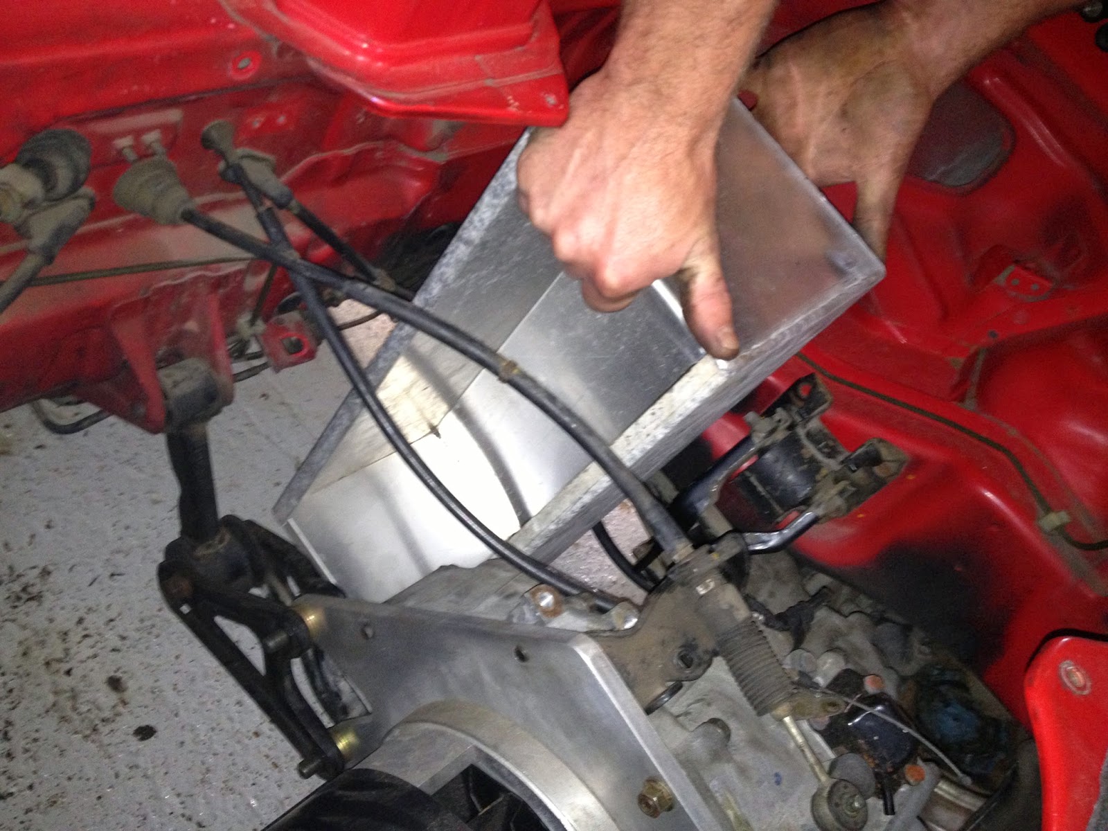
Aluminum battery boxes finally built

At last I found a local sheet metal fabricator that was happy to use my old sheets of aluminum (well my partner did anyhow as she is definitely in control of the finances on this project), David from Sussex Iron Works, literally just down the road from me.

After supplying him with the hand drawn technical drawing that Mikki (My Partner) had kindly produced from Brents rough sketch, he got straight to work on them the next day, the day after that they were done and for less than half the price I was originally quoted (£200 to be exact) this is great as not only did I save money but got to use some very old sheet Ali I have had kicking around for years.

I will post photos of these soon as well.


I took the boxes straight back to Brent for sizing up against the car so we can work out exactly where the Ali angle needs fitting to give us a mounting solution.


Brent was on holiday that week so I caught up with him the following week and talked at length on the next stage in the build.

Brent advised me of the need to make up a steel support frame to hold the battery boxes securely in place, I had originally thought that we could just mount the angle Ali straight onto the car but as Brent explained this would be very insecure and in the event of a crash would definitely not be good enough to prevent the battery’s flying out everywhere ( I am learning more every day on this project).

He has ordered the Steel and it should be here on Friday (Today in fact) his next free slot for the EV project was next Wednesday and he reckoned that it should not take more than a day to make up the steel support and size up the boxes ready for TIG welding of the Ali Brackets, so they should be ready for battery stuffing the week after that (hopefully)

Monday, 20 May 2013

3D Printing parts for the 10KW charger build

After spending a brief lunch break over at the mechanics last week I roughed out a box in cardboard to give me an accurate idea of how much space I have in the micro boot on the Honda Beat to fit the charger into, I will be using the right hand half of the mini boot space for the charger, this will give me simple access to the charger (for charging) accessed via the boot which should be ideal for charging, I also hope to put a “Standard” (there are several standards by the look of it) socket for connecting the power to charge into the ex-fuel filler cap.
The left hand half of the mini boot space will hold the Soliton, by coincidence there is an access plate from the mini boot into the main “Engine” area of the car this access plate is exactly the right size to hold the Soliton, Brent was considering mounting the Soliton directly on this plate which is cool as it would make removal of the Soliton easy if necessary.

I am also thinking this is a good plan, so once I got the box home and considered how I might make (fold) a box out of 3mm Ali, I moved onto roughing out the part placement for the charger.

It looks like it will be fairly straight forward, I am intending to mount the very large single capacitor onto the rightmost wall of the charger box using 3D printed brackets which I constructed in 3D using OpenSCAD, after making a simple hoop strap with mounting bar and holes (photo coming soon) and printing it I then decided to modify the second strap into a cap for the “Dangerous” connection end of the very large capacitor, this will protect the bare connections from accidental shorting if anything comes lose in the charger box whilst driving, I also intend to mount this large capacitor connection end down also for safety sake (although this is not absolutely necessary if I am going to “cap” the Capacitors connection end, so this could change)


Very large capacitor with 3D printed bracket & bracket-cap

I have also been thinking how I will mount the toroid transformer (also very large) it needs to be close but not touching the heat sink and the air flow needs to be unrestricted by any mounting solution, the instructions with the charger build suggest using a sheet of thick HDPE and cutting “C” brackets from this, this is a no brainer for 3D printing as I could print HDPE if I needed to although ABS should be fine as there is little difference in heat tolerance of these 2 thermoplastics.

I will fabricate a CAD toroid mount bracket which has fins that slide between the veins of the heat sink with a ring the same size as the toroid fixed to these fins I can then mount 2 (or 3) “C” brackets that are joined to the ring and hold the toroid from moving anywhere, this should give me a firm mount with plenty of heat dissipation capability.

Toroidal 3D printed bracket on printer with support 
 
Toroidal 3D printed bracket support removed

This does meant that my charger component placement will be a little unusual but this is a consequence of the size of the box I have to fit this into and the need for serious cooling when the car is charging.

Brent tells me he can drill out the old battery plate that sits in the bottom of the mini boot where the old 12V car battery used to be located, this will give me a few extra mm of height which is going to be required to get it all in if I want a lid for the charger, which I will as the charger controls will be mounted on the lid.

But all in all it looks like it will all fit quite nicely.

Lots more photos coming as soon as I figure out why my canon camera has suddenly refused to be recognized by my PC!

Thursday, 16 May 2013

Battery Box discussions

Spoke to Brent last night on what he had discussed with Steve about the battery box placement and sizes/costs etc.

It looks like it is going to work out quite nicely, it seems I will have 3 battery boxes, 1 each side of the forward motor mount, and a third in the front bonnet underneath the spare wheel (should be able to retain the spare wheel and tray in the flip forward style bonnet)

He also said that he had mocked up the boxes and sent the details to the box fabricators (TIG weld specialists) and that they were getting back to him with prices, he also thought that they would not be happy to use the old “Dirty” Ali that I have and that they would probably want to use new Ali to avoid any extra time being wasted cleaning the Ali before welding.

Ho Hum, it seems that welders just like builders don't like to reuse and recycle! Oh well it is more important to me now to just get the boxes made pronto as I am desperate to not have the build stall for any reason, so I will probably just go with the welders Brent uses depending on cost. 

Brent was concerned about me supplying the charger for sizing purposes as he need to know if there is any more cutting of the boot required before they begin jet washing the underneath and wire brushing ready for under sealing (I have specifically requested this as I need the car to last 10 years to be economically viable)

I have told (guaranteed) Brent that I could make the charger fit the right hand side of the “mini” boot without the need to cut anything, I am going to pop over to the mechanics this lunchtime to mock up a box in cardboard so I can be sure I can fit the space available, I also need to make sure that I can cool the charger effectively, I will discuss options for this with Brent, there is a convenient fan sized hole right where the charger will go that I hope to use for air cooling with a fan/s.

Brent also mentioned the need for a transformer to convert the output from the Soliton JR to 12V (it does not supply this) Brent thought that I should already know about this (I do remember a brief discussion with Steve on this but was not aware of extra parts required, I will check this with Steve).

Motor & Gearbox fitted

I visited the Mechanics last Friday 10th May to take a look at the Motor and Gearbox fitted (temporarily), took lots of photos


Series of Photos showing motor fitted (temporarily)
with custom steel mounting brackets courtesy of SMD (Brent & Luke)
The green MG is underneath the Honda which is up on the lift.

Brent had made up some custom steel motor mounts also fitted and discussed the need to get the batteries over for sizing up the battery trays, along with the rest of the bits.

We will be removing everything and cleaning the (very dirty) car inside and out before prepping, rust protecting, (although there is very little rust considering this is a 20 year old car!) and under sealing.

If I am not bankrupt by the time I have finished this build I would also love to get just the outside prepped and re-sprayed in metallic black ready for some decals or maybe a whole car wrap graphic (sweet).
I immediately mailed Steve from Jozztek asking for some batteries for sizing purposes and updating him on the swift progress recently.

I dug out the 2 sheets of 3mm Aluminum this weekend, they turned out to be 6x4 (foot) sheets rather than 8 x 4 as I had remembered  but there should be enough for the boxes.

Steve has just mailed me to say he will be catching up with Brent tomorrow (Tuesday 14th) to give him the batteries (for box sizing) and to discuss details mounting positions etc.

I must now get busy with the charger build.

Friday, 3 May 2013

Coupling plate & splined “low inertial” coupling made & fitted

Called Brent yesterday to check on progress and discovered that he has received the motor/gearbox back from the CADCAM engineer as of Thursday 2nd May.

We (Brent) decided that it would be simpler for the CADCAM engineer who was tasked with milling the coupling plate & splined collar to supply the motor & gearbox coupled, avoiding potential mistakes in manufacture or fitting of the plate & collar.

Brent tells me that he is collecting the Honda from me next Tuesday for fitting of the motor /gearbox into the Honda Beat.

Then we should be ready for Steve (Jozztek) to take a close look at where best to position the controller pack (Soliton Jr)  the Charger & Battery Boxes/Trays, my friend  who was going to do the TIG welding has now gotten held up on other business so it looks like I will have to find another TIG welder (person) but all in all things are really starting to move forward on the build now, I am still hoping I may get to drive this beauty before summer is over, after all it is a convertible.

I will try and visit the mechanics tonight to get some photos of the Motor/Gearbox before it is fitted.

Wednesday, 17 April 2013

EV build begins at last

The mechanics have been rather busy of late and the EV build has been pushed back a few weeks, however they collected the engine from me yesterday (16th April) and have begun the build proper today (17th) by coincidence I bumped into my mechanic this morning in the petrol station and he was in the process of taking the measurements of the engine to motor coupling plate over to the machine shop for the mechanist to mill up the coupling plate and splined collar, Brent has assured me that this should only take a couple of days to manufacture (on a CAD CAM mill) and they will be fitting the motor to the gearbox and fitting this back into the car, I am hoping that this will all be done by the end of this week.

Also I have been speaking with a friend of mine who has some experience of TIG welding and he has agreed to have a go at making up the battery boxes from a couple of 8 x 4 sheets of 3mm thick aluminum that I have had kicking around for years, we should be able to cut out all the Battery Box parts and clean them up a bit ready for  welding , I am also going to get a box made up for the charger (which I am still building) from the same sheets of aluminum.

So all in all things are starting to move in the right direction, I hope that the car will be back with me (motor & gearbox fitted) by the end of this week (optimistic in my opinion) so that I can get Steve (my EV specialist) to have a looksee at where we are going to put the rest of the bits (Charger/Battery boxes/Soliton Jr etc).

Exiting times!
Kostov K9 220v Motor still in box and Soliton Jr fresh out the box

Wednesday, 27 February 2013

Engine & Ancillaries stripped

My partner has christened the EV “Electro Beat”, the Donor car went in on the 11th of Dec for the engine removal, unfortunately it looks like I may have to keep the gearbox due to space & cost issues, this is not definite yet as we may be able to mod the gearbox so as we are just using the gearbox casement which is useful as it has all the engine mounts connected to it so we would not have to make potentially expensive custom engine mountings.

Worst case is we keep the gearbox & gears complete and I would just have to use the 4th& 5th gears, this is a tried and tested method and although it is a simple low cost solution it will result in additional noise from the gearbox (whir, which would normally be covered by the loud engine noise) and the loss of some torque through the gearbox as friction & noise.

My mechanic (Brent) took the beat for a test drive before he started the strip down and laughed at just how underpowered it was, after all this little car only developed 63BHP new and looking at a more recent dyno readout that was supplied with the car (handy!) this one was nearer 57BHP, my limited experience of driving this great little car (picking it up) was similar in it seemed to make a hell of a lot of noise for very little grunt. But all the same a great fun car to drive and being a Honda it has rock solid build quality.

Anyway the motor is due to be ordered at the end of December so I should be getting the joiner plate and a coupling made up once this has arrived (Probably around mid Feb).

I will put the engine & ancillaries up for sale after the motor is fitted as I may need the flywheel from the engine side to make the coupling to the motor easier.

If it turns out I don't need the gears in the gearbox I may also sell these as they seem to fetch a price secondhand as they are very difficult parts to come by if you need one.

At the mechanics just before stripdown
 
Exhaust removed
 
 
 Engine & Cooling system out